555 Timer Circuit Schematic / Inverted 555 Timer CircuitElectronics Project Circuts / Decade counter 4017 counts the incoming pulses and activates its outputs i.e.. Its not listed anymore, but i can still link it in. Here, the 555 timer runs in astable mode. It is available for free download. This principle is used in a comparator circuit with two inputs and an output. Just check the pinouts of the pot.
They provide access to some basic and important components too. This principle is used in a comparator circuit with two inputs and an output. For the first pulse q0 becomes high and for second pulse q1 becomes high and so on again for 10th pulse q0 state becomes high. It is available for free download. The 2 inputs, out of which one is a reference voltage (vref) is compared with each other.
555 Timer Monostable Circuit Diagram from circuitdigest.com In rain alarm circuit, the main reason behind using 555 timer ic is to trigger the buzzer for producing oscillating sound. Its not listed anymore, but i can still link it in. Here, the 555 timer runs in astable mode. The second main component of this circuit is 555 timer ic. You can explore various applications based on monostable multivibrator in 555 timer circuits. A tutorial on how to make an adjustable delay timer circuit using 555 ic that can automatically turn on/off any output after a fixed duration. Just check the pinouts of the pot. The 2 inputs, out of which one is a reference voltage (vref) is compared with each other.
A tutorial on how to make an adjustable delay timer circuit using 555 ic that can automatically turn on/off any output after a fixed duration.
The second main component of this circuit is 555 timer ic. The 2 inputs, out of which one is a reference voltage (vref) is compared with each other. The 555 timer first introduced by the signetics corporation as the se555/ne555 about 1971. Decade counter 4017 counts the incoming pulses and activates its outputs i.e. Just check the pinouts of the pot. A tutorial on how to make an adjustable delay timer circuit using 555 ic that can automatically turn on/off any output after a fixed duration. Here, the 555 timer runs in astable mode. Sep 29, 2015 · you can also calculate the t with this 555 timer monostable calculator. For the first pulse q0 becomes high and for second pulse q1 becomes high and so on again for 10th pulse q0 state becomes high. Although, these component symbols change based on countries due to some common principles fixed by ansi & iec to signify the components. Above schematic diagram shows the 555 timer monostable multivibrator circuit. It is available for free download. Jun 10, 2021 · there is a 555 timer application on this site to achieve the timings you need.
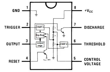
The simplicity of the timer, in conjunction with its ability to produce long time delays in a variety of applications, has lured many designers from mechanical timers, op amps, and various discrete circuits into the ever increasing ranks of timer users. Here, the 555 timer runs in astable mode. A tutorial on how to make an adjustable delay timer circuit using 555 ic that can automatically turn on/off any output after a fixed duration. Description the 555 timer consists of two voltage comparators, a bistable This principle is used in a comparator circuit with two inputs and an output.
555 timer circuit diagrams | different modes of 555 timer from i2.wp.com Just check the pinouts of the pot. Description the 555 timer consists of two voltage comparators, a bistable Decade counter 4017 counts the incoming pulses and activates its outputs i.e. Jun 10, 2021 · there is a 555 timer application on this site to achieve the timings you need. The 2 inputs, out of which one is a reference voltage (vref) is compared with each other. Above schematic diagram shows the 555 timer monostable multivibrator circuit. This principle is used in a comparator circuit with two inputs and an output. It supports circuit drawing, layout developing and circuit simulation.
Description the 555 timer consists of two voltage comparators, a bistable
The 555 timer first introduced by the signetics corporation as the se555/ne555 about 1971. Jun 10, 2021 · there is a 555 timer application on this site to achieve the timings you need. Decade counter 4017 counts the incoming pulses and activates its outputs i.e. Here, the 555 timer runs in astable mode. In rain alarm circuit, the main reason behind using 555 timer ic is to trigger the buzzer for producing oscillating sound. Electronic circuit symbols are signs or drawings or pictograms of different components to signify electronic components in a schematic diagram of an electronic circuit. The simplicity of the timer, in conjunction with its ability to produce long time delays in a variety of applications, has lured many designers from mechanical timers, op amps, and various discrete circuits into the ever increasing ranks of timer users. Its not listed anymore, but i can still link it in. It is available for free download. They provide access to some basic and important components too. Just check the pinouts of the pot. For the first pulse q0 becomes high and for second pulse q1 becomes high and so on again for 10th pulse q0 state becomes high. Sep 29, 2015 · you can also calculate the t with this 555 timer monostable calculator.
Just check the pinouts of the pot. Jun 10, 2021 · there is a 555 timer application on this site to achieve the timings you need. The second main component of this circuit is 555 timer ic. It supports circuit drawing, layout developing and circuit simulation. The simplicity of the timer, in conjunction with its ability to produce long time delays in a variety of applications, has lured many designers from mechanical timers, op amps, and various discrete circuits into the ever increasing ranks of timer users.
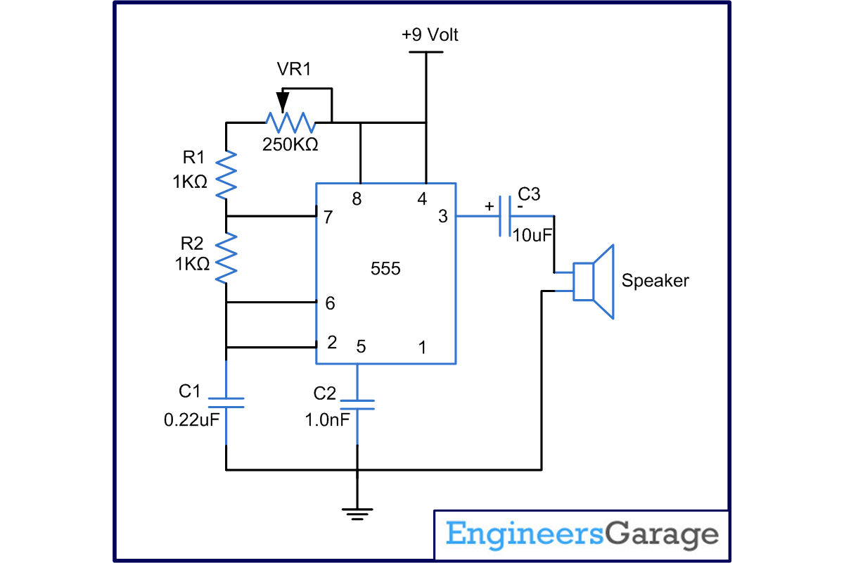
Metronome using astable mode of 555 timer IC from www.engineersgarage.com The simplicity of the timer, in conjunction with its ability to produce long time delays in a variety of applications, has lured many designers from mechanical timers, op amps, and various discrete circuits into the ever increasing ranks of timer users. The second main component of this circuit is 555 timer ic. This principle is used in a comparator circuit with two inputs and an output. Sep 29, 2015 · you can also calculate the t with this 555 timer monostable calculator. The 2 inputs, out of which one is a reference voltage (vref) is compared with each other. Description the 555 timer consists of two voltage comparators, a bistable Decade counter 4017 counts the incoming pulses and activates its outputs i.e. Jun 10, 2021 · there is a 555 timer application on this site to achieve the timings you need.
Although, these component symbols change based on countries due to some common principles fixed by ansi & iec to signify the components.
You can explore various applications based on monostable multivibrator in 555 timer circuits. The 2 inputs, out of which one is a reference voltage (vref) is compared with each other. A tutorial on how to make an adjustable delay timer circuit using 555 ic that can automatically turn on/off any output after a fixed duration. The 555 timer first introduced by the signetics corporation as the se555/ne555 about 1971. They provide access to some basic and important components too. It supports circuit drawing, layout developing and circuit simulation. It is available for free download. The simplicity of the timer, in conjunction with its ability to produce long time delays in a variety of applications, has lured many designers from mechanical timers, op amps, and various discrete circuits into the ever increasing ranks of timer users. Decade counter 4017 counts the incoming pulses and activates its outputs i.e. Nov 03, 2018 · the circuit uses 555 timer and a decade counter ic cd4017. Jun 10, 2021 · there is a 555 timer application on this site to achieve the timings you need. Here, the 555 timer runs in astable mode. Its not listed anymore, but i can still link it in.
Electronic circuit symbols are signs or drawings or pictograms of different components to signify electronic components in a schematic diagram of an electronic circuit 555 timer schematic. This principle is used in a comparator circuit with two inputs and an output.


0 Komentar